This chapter describes the status of the many components of the Sloan Digital Sky Survey (SDSS) as of Thanksgiving 1996; much more detail on the design, construction and performance of the individual components is given in the following chapters. An overview of the entire project in flow-diagram form, from light entering the telescope to data archived for science analysis, is given in Figure 4.1. The photometric data are collected at the Apache Point Observatory (APO) by the 2.5 meter telescope with its camera, and shipped by express carrier to Fermi National Accelerator Laboratory (FermiLab) for reduction, together with photometric calibration data from the Monitor Telescope (MT). The reduced photometric and astrometric data with their calibration information are written to the Operational Data Base (ODB) and to the Science Data Base (SDB); the former runs the survey and the latter is a read-only archive accessible by the project participants for science analysis. The target selection pipeline then selects astronomical objects for spectroscopy, as described in Chapter 3, and designs a fiber plug plate for each spectroscopic field. The plug plates are drilled, plugged at APO, and the spectroscopic fields observed. The spectroscopic data are reduced at FermiLab and the spectra and redshifts recorded in the data bases.
The original installation of utilities and infrastructure at APO, which began in 1984, was planned to accommodate three large telescopes, of which the first was the Astrophysical Research Corporation (ARC) 3.5 meter. The site, and its suitability for this project, are described in detail in Chapter 7. The long-term plans filed with the National Forest Service, which controls the permit for use of the site, included plans for additional dormitories, roads and office space as later expansion items. The details of this construction were allowed to be driven by the requirements of the new projects. It was thus straightforward to accommodate the needs of the SDSS project as an expansion of the site within these plans.
The SDSS telescope enclosure was erected on its site in Summer 1994, and the necessary utility connections and hookups were made at this time. At the same time, the main operations building for the 3.5 meter telescope was expanded by 3000 square feet to provide additional laboratory, office, operations and meeting space. The original APO darkroom was rebuilt as a laboratory for handling SDSS and has now been upgraded to clean-room status in readiness for the arrival of the photometric camera in Spring 1997. A new dormitory was built. The enclosure for the monitor telescope (MT) was erected ENE of the 2.5 meter telescope enclosure and a building ESE of the 2.5 m telescope was erected for the handling of the fiber plug plates. Additional trenches were dug for cabling and utilities for these new buildings.
The loading dock to the operations building was improved to allow easy movement of instruments back and forth between the 2.5 meter telescope and the laboratories. Provision for a large SDSS control room was added to the operations building, and enough new lab space added to provide adequate support for both telescopes. Extra kitchen, laundry and office space is now in place, and has allowed the average steady state personnel presence to grow from 5 to 10. The extra personnel load during the integration and commissioning of the SDSS hardware will be accommodated by off-site living space and on-site trailers to serve as temporary office space.
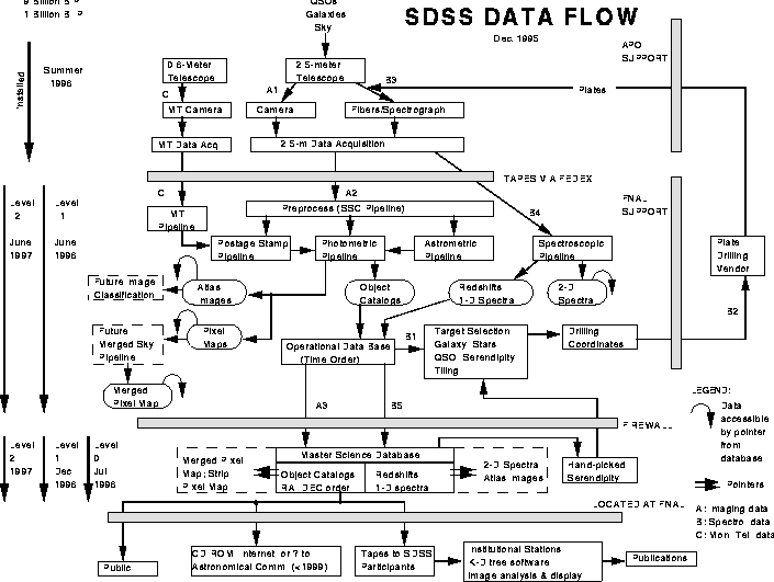
Data flow through the SDSS.
The site is served by a leased T1 communication channel to New Mexico State University (NMSU) and from there via Internet to the ARC/SDSS institutions. This link will be shared by SDSS for project personnel communications.
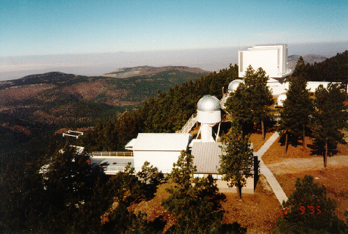
View of the SDSS 2.5 m and ARC 3.5 m telescopes from the south.
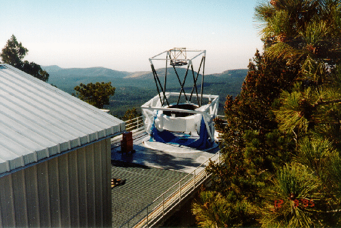
The SDSS 2.5 m telescope from the east.
Figure 4.2 shows the site from the south. The closest buildings are the white 2.5 m telescope enclosure and, to its right, the plugplate support building. The upper part of the 2.5 m telescope itself can be seen to the left. The small silver dome behind the plug plate building houses the Monitor Telescope, and the larger white dome housing the ARC 3.5 meter telescope is seen to the upper right. Figure 4.3 shows the 2.5 m telescope on its pier and looks west over the White Sands National Park.
Located under the site are an electric ground plane, a sewage drainage facility and a water storage and distribution system for fire safety. The APO staff participate in the local volunteer fire departments and safety organizations which are essential for site safety in remote regions. Drinking water is purchased from the National Solar Observatory (NSO) in Sunspot, NM, at local rates. All other utilities are provided by contract between local prime suppliers and NMSU/ARC.
In general, staff at APO are shared between the SDSS and the 3.5 m telescope under the supervision of the Site Manager. The on-site staff at APO provide management, computing, engineering and observing support. Services for plumbing, carpentry, electrical work, machine shop work and snow removal are purchased from NSO. Local contractors are available for large machining jobs (at High Rolls, NM, 40 minutes from the site) and for standard building and construction work (at Cloudcroft, 30 minutes away, or Alamogordo, 60 minutes away). Additional shop work and some optics work can be obtained from the laboratories of the U.S. Army at the White Sands Missile Range, 75 minutes away. APO and NSO have an arrangement for mutual backup of computing systems administration.
The overall responsibility for staff allocation, personnel issues, human safety and site resource management rests with the APO site manager. ARC provides funds to NMSU for all site expenses, which are managed by the Site Director, who is also the NMSU Principal Investigator for the ARC/NMSU operations agreements. Purchasing, site insurance, bookkeeping and related items are provided by NMSU on a for-fee basis. ARC and NMSU re-negotiate the site agreements every three years.
In summary, the physical infrastructure and management are in place at the APO site to support the SDSS. The process of hiring operators for the survey is now underway.
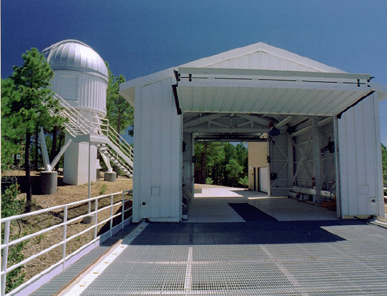
The 2.5 m telescope enclosure. The monitor telescope dome is seen to the left.
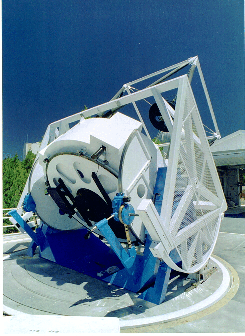
The 2.5 m telescope. This view shows the azimuth bearing and the location of the spectrograph mounting. The rolled-off enclosure can be seen to the right.
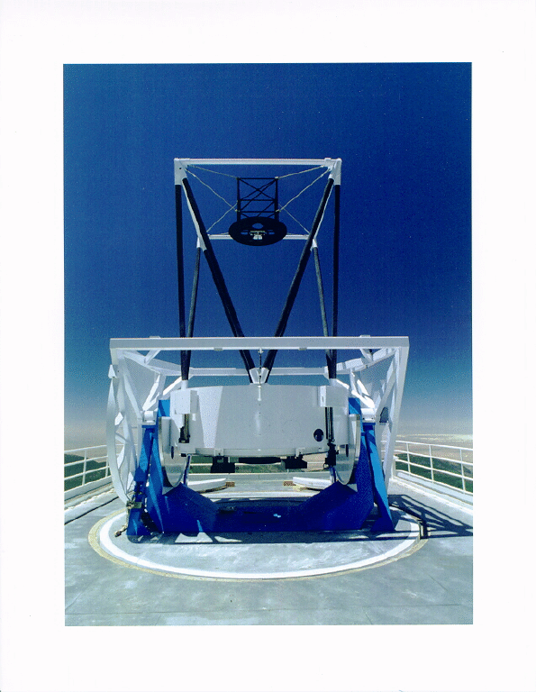
The 2.5 m telescope.
The design of the telescope is described in detail in Chapter 6. The main telescope construction contracts are complete. The telescope structure was installed in October 1995, and is shown in Figures 4.3, 4.4, 4.5, and 4.6. The exterior wind baffle is substantially complete, and is in storage at the vendor's shop, about 40 minutes from the site. It will shortly be fit-checked, then stored until the optics have been installed. The interior light baffles are in fabrication and are scheduled to arrive at APO in Spring 1997.
The telescope controls are still in the detailed design stage. The design is based on programmable off-the-shelf components and on the 3.5 meter telescope control system, with improvements suggested by experience with the 3.5 meter. The safety interlock system is in the detailed design stage, and will be the last item installed; in the meantime, we expect the first tests of the telescope control system to use safety check lists for the operators. The telescope control computer, a duplicate of that used on the 3.5 meter telescope, has been installed. Since the operating system and design of the two telescopes are very similar, much of the experience gained in operating the 3.5 meter telescope can be applied to the 2.5 meter. For example, drift scanning has been tested and verified on the 3.5 meter telescope, and the pointing correction algorithms used by the 3.5 meter have been installed on the 2.5 m.
Careful attention was paid at all stages to the performance of the telescope components, by measuring the precision of each component before and after installation. As a result, the contribution of the telescope structure to the cumulative tracking error is < 0.1 arcseconds. The telescope design will allow tracking precision three times better than this, but this implementation must await tests with a working telescope.
The telescope has three large optical elements: the primary and secondary mirrors and the common corrector lens. In addition, there are correcting lenses for the instruments. The primary mirror is at the site, has been aluminized and is being prepared for installation. The secondary mirror is at the site and aluminized. The figuring of the common corrector is complete, and this element is at the vendor for anti-reflection coating. The figuring and of the spectrographic corrector are done. The photometric corrector is finished and coated; it doubles as the mounting structural element for the camera, whose status is discussed in more detail below.
Still to be done are the installation and commissioning of the telescope control system, the installation of the optics and the alignment of the optics. We currently expect first light (with the photometric camera mounted) in Summer 1997.
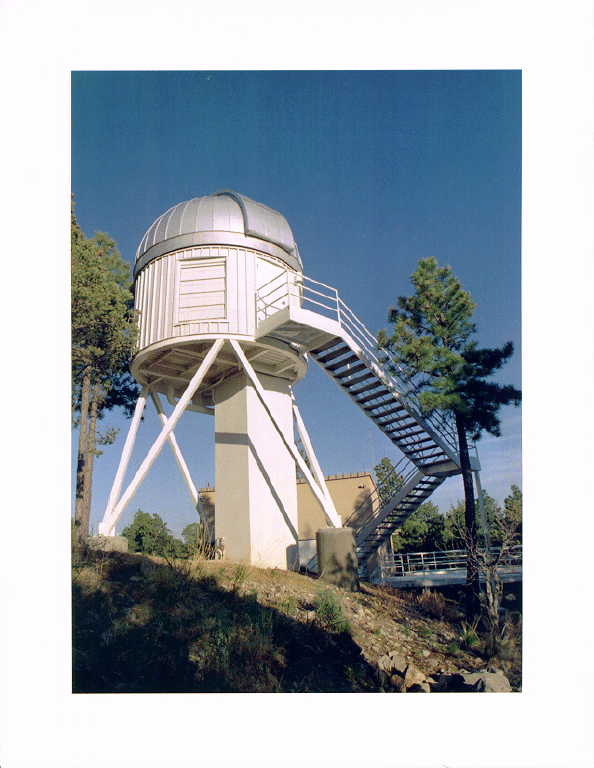
The enclosure for the 0.6m monitor telescope.
The monitor telescope (MT) enclosure (see Figures 4.7 and 4.8) was erected in 1994 and the 0.6 meter MT installed in June 1995. The CCD camera and filter wheel were installed in late 1995. The design and purpose of this telescope are described in detail in Chapter 9.
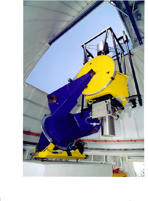
The monitor telescope with its CCD camera.
Commissioning of the telescope is nearing completion. The telescope optics have been recoated to match the spectral response of the photometric camera quite closely (the photometric camera uses both thinned and unthinned CCDs, while the MT camera uses a thinned chip). Good progress is being made towards fully automated operation over a whole night, and the monitor telescope pipeline (which reduces the MT data at FermiLab) has been installed at APO to aid in the commissioning. The MT camera electronics have been replaced to fix a problem with excess readout noise. The MT should become operational in Spring 1997, and at this point the telescope will be finally aligned and collimated. It is hoped that the MT will be ready for routine operation in early 1997 to set up the primary standard star network; when routine operation is achieved the MT will begin setting up the calibration patches.
The SDSS has installed a 10 µm cloud-cover monitor at the site; this instrument has proven very useful for 3.5 meter telescope operations. We are in the process of comparing its images with determinations of the photometricity of given nights, from observations of standard stars.
The camera is described in Chapter 8. The photometric array consists of 30 photometric CCDs, in six columns of five rows, each row to observe through one of the five survey filters. The 24 astrometric CCDs form two arrays at the leading and trailing edges of the camera, and include two CCDs to measure the focus and tracking. The photometric corrector lens is a structural element of the camera; the filters are glued to it and the six photometric and two astrometric dewars, which contain the CCDs, the readout and control electronics and the cooling system, are mounted directly to the corrector via cemented threaded inserts and attachment bars. The camera electronics include the FOXI chips, supplied by FermiLab, which transfer the data from the CCDs to the data acquisition system.
The camera is now in an advanced stage of assembly. All electronic design is complete, and all electronic fabrication work has been completed and delivered. All of the electronic components have been thoroughly tested before and after assembly.
All optical fabrication is complete and the filters and spacers are bonded to the corrector. The corrector has been placed in its support. All mechanical fabrication is complete and the assembly tests are done. The dewars are now being assembled and tested. The shutter is fabricated and is being tested. The cable harness, mounts for the electronic and cooling systems and the cart which transports the camera between the telescope and the storage facility at APO are all assembled. All specifications on the optics figuring, the optics transmission and the mechanical stability have been tested, met and verified.
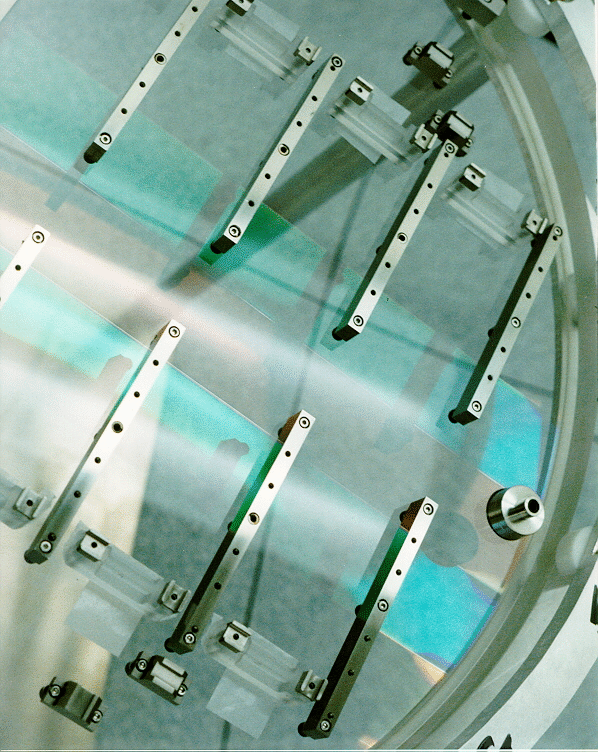
The photometric corrector with the mounting bars for the CCD dewars. Note the anti-reflection coating strips; the coatings are different for each row of filters.
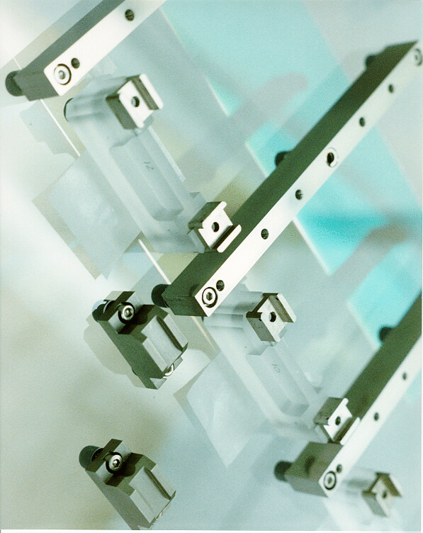
Closeup of the mounting sockets for the photometric and astrometric dewars.
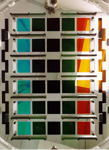
The photometric corrector with the filters glued in place. The "crenellated" rows of filters at either end of the photometric array are the r' and neutral density filters for the astrometric CCDs. The photometric filters from left to right are g' , z' , u' , i' , and r' .
Figures 4.9, 4.10 and 4.11 show the camera at various stages of assembly.
The CCDs plus spares are all in hand, and the quantum efficiency, noise figure and cosmetic quality of all of the CCDs have been measured, tested and characterized. The CCDs have all been bonded to the mountings which allow their orientation and tilt to be aligned and adjusted.
Scientists from the Japanese Participation Group (JPG) have built a device to measure the quantum efficiency as a function of wavelength with a resolution of 10 Å, and baseline measurements have been made of all of the CCDs. These will be repeated when the camera is assembled and periodically during the operation of the camera at APO.
After full assembly and testing at Princeton, the camera will be partly dis-assembled, shipped, then re-assembled in the clean room at APO. The camera is currently scheduled to be shipped in early 1997.
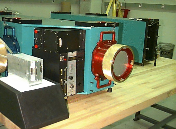
One of the two double spectrographs in the lab at JHU. The red and blue sides of the spectrograph are color-coded.
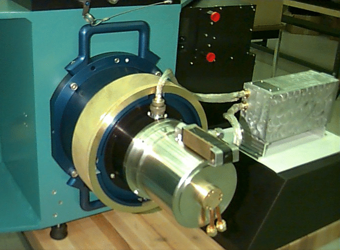
Blue side of the SDSS spectrograph with the CCD camera.
The two double spectrographs, described in Chapter 11, were designed, constructed, assembled, and tested at the Johns Hopkins University (JHU). and the four CCD cameras were made at Princeton. The cameras and camera electronics have been completed and shipped to JHU. The CCD electronics have been successfully integrated with the data acquisition system (DA) at APO. The first of the two spectrographs has arrived at APO, while the second remains at JHU for final optical testing. The spectroscopic mounting has been successfully fit-tested on the 2.5 meter telescope. Figure 4.12 and 4.13 show two views of the spectrographs in the labs at JHU. The dewars and mounting rings are anodized red and blue to correspond to the red and blue camera ports.
Throughout the construction of the spectrographs, all optical efficiencies have been maintained at better than specification, as have all measured tolerances on the gratings. The mechanical machining and assembly specifications have been met and verified. The performance of the CCD cameras is at, or exceeds, specification.
Spectra are taken by positioning fibers in the telescope focal plane using plug plates. The plate drilling plan is finished, and all required tolerances for hole diameter, shape, tilt, cleanliness and placement have been verified as achievable by two commercial vendors as well as in the University of Washington (UW) shops. The fixtures used to bend the plates in the drilling machine and to bend the plates (in the opposite direction) on the telescope have been demonstrated to give accurate positioning of the fibers in the focal plane. Test plates corresponding to real positions of galaxies have been made, and simulations done to determine that the fibers as installed in their cartridges have adequate reach. Tests and investigations are underway to ascertain the completeness level of the plugging and the effects of tangling.
The fibers and cartridges (which restrict the flexure to an amount which will not damage the fiber) have been ordered. The first set arrived in October 1996 and the sets will continue to arrive at a rate of about one per month for the next year or so. The bid followed extensive testing to be sure that multiple use would not degrade the fibers and that the tips, polishing, beam divergence and transmission were up to specification. The fibers are delivered individually polished and mounted in packages of 20 attached to slits, with tips and cladding on the plug plate end. The fibers are mounted to slit plates at UW, affixed to slit heads and threaded into position on the cartridges.
The computer hardware and software required to acquire the data and write it to tape have been installed at APO and were successfully integrated with the CCD camera electronics (including verification of simultaneous readout of five photometric CCDs) in October 1996. The equipment includes the VME microcomputers, redundant DLT 200 drives, scrolling monitors to show the real-time output of each photometric CCD, enough disk space to hold 40 minutes' worth of photometric data (about 12 GB) for quality control and monitoring purposes, and cabling, power and racks.
The software includes rudimentary command control of the instruments, a quick-look toolkit for simple manipulation of the data, and programs to output the data stream to disk, tape etc. The cabling and racking of the DA system were completed in October 1996. It is likely that most of the testing of the camera will be done at the site, using the DA system, before the camera is mounted on the telescope. Operations and DA software installation is also complete for the MT.
The software which reduces and calibrates the SDSS data, carries out target selection and archives the data is written in modular form as a series of pipelines which are integrated and run together in the DERVISH environment (Chapter 14). The software has been developed and tested by scientists at the SDSS institutions and is organized under CVS (Concurrent Version System).
The development of each software component is organized in four stages: prototype, Level 0, Level 1 and Level 2. Level 1 is the code containing the entire functionality and extensively tested on detailed simulations which is taken into commissioning and the test year. During the test year, the algorithms are refined and optimized to handle real data, and are then "frozen" as Level 2 for the start of the survey proper.
An intensive effort has been made to produce simulations of the survey to aid integration and testing of the algorithms before real data from the 2.5 meter telescope becomes available. The software also includes a detailed data model, to keep track of the changing outputs of the pipelines.
The pipelines are typically developed by one group and tested by another. A large computer (the "production machine") has been acquired at FermiLab to run the survey, and the pipelines have been successfully ported to this machine. At this point (November 1996) the software is with a few small exceptions ready to receive data from the 2.5 meter.
The operating environment, DERVISH, integrates the data reduction pipelines and also contains an extensive toolkit for display, analysis and debugging. It has been operated at Level 1 for about a year.
This pipeline calibrates the positions of stars between 14m and 15m with reference to the astrometric standard network. It is written and tested by two groups at the United States Naval Observatory (USNO) and is complete to Level 1.
This pipeline reduces the data from the MT and produces photometric calibrations for the data from the photometric camera. It is written at FermiLab and Princeton and tested by the JPG. It is complete to Level 1.
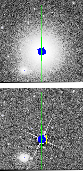
Example of automated photometric data reduction by Photo. Top: simulated CCD image of a field containing a bright star. Bottom: Image with bright star subtracted.
The largest of the pipelines, Photo reduces the data from the photometric camera and produces reduced images and object catalogs. With the exception of one remaining task (deblending overlapping images) Photo is complete to Level 1. An example of Photo's output is shown in Figure 4.14. It is written at Princeton and tested by the JPG. Astrom, MTpipe and Photo have been successfully integrated for more than a year.
Based on Photo's outputs, TS selects objects for spectroscopy. The code is done at Level 0 and many of the algorithms are in place at Level 1. It is written at FermiLab and tested by David Weinberg (Ohio State).
Spectro reduces the spectroscopic data and calculates calibrated spectra, with redshifts and other parameters. Spectro is at Level 0, some of the Level 1 code is in place, and the code will shortly be ready for testing and integration. Spectro is written at Chicago and is to be tested at Princeton.
Strategy designs the plug plates, generates a drilling plan, does bookkeeping for the survey and designs and updates observing plans to maximize the rate at which the sky is covered. Some parts have been finished for about a year, others are still under development.
The ODB contains the outputs from the pipelines in a commercial object oriented data base. It resides in a Silicon Graphics Challenge at FermiLab and maintains the database and data model, applies calibrations, runs target selection and maintains a history of calibration and target selection. The ODB is at Level 0 and has recently been successfully used to run TS.
The science data base contains the calibrated SDSS data under an object oriented data base with rapid, efficient access and query and visualization tools. It is written at JHU and is expected to reach Level 1 in early 1997. The SDB will develop into the tool for public distribution of the SDSS data.
The schedule for the delivery of the remaining components and their installation at APO is shown in Chapter 16 (Figure 16.1). The telescope and camera are expected to be functioning together and ready to take data by Summer 1997. An extensive period of commissioning will follow, with a well-defined set of performance goals to be met before the survey can begin. Staffing at the full operations level will be necessary beginning early 1997.